
1.0 Connector basics
Connectors are a kind of component that our electronic engineers and technicians often come into contact with; Its function is very simple: to build a bridge of communication between the blocked or isolated circuits in the circuit, so that the current can flow, so that the circuit can achieve the intended function. Connectors are an indispensable part of electronic devices, and if you look along the path of current flow, you will always find one or more connectors. The form and structure of the connector are ever-changing, with the application object, frequency, power, application environment, etc., there are various different forms of connectors; For example, the connector used to light the lights on the pitch is very different from the connector used for the hard drive, and the connector used to ignite the rocket. But no matter what kind of connector, it is important to ensure that the current flows smoothly and reliably.
2.0 Why do you need to use connectors?
Imagine what it would be like without connectors? At this time, the circuit should be permanently connected together with continuous conductors, for example, if the electronic device is to be connected to the power supply, both ends of the connecting wire must be fixed and firmly connected with the electronic device and the power supply through a certain method (such as welding); In this way, it has brought a lot of inconvenience to both production and use.
Take car batteries, for example; Assuming that the battery cable is fixed and welded to the battery, the automobile manufacturer will increase the workload and increase the production time and cost for the installation of the battery; When the battery is damaged and needs to be replaced, the car must be sent to the maintenance station, the old one is removed from the welding, and the new one is welded on, for which more labor costs have to be paid; With the connector, you can save a lot of trouble, buy a new battery from the store, disconnect the connector, remove the old battery, install a new battery, and reconnect the connector; This simple example illustrates the benefits of connectors; It makes the design and production process more convenient and flexible, and reduces the production and maintenance costs.
3.0 Advantages of connectors
Improve the production process
Connectors simplify the assembly process for electronics. It also simplifies the mass production process
Easy to repair
If an electronic component fails, the failed component can be quickly replaced when the connector is installed
Easy to upgrade
With the advancement of technology, the components can be updated when the connector is installed, replacing the old ones with new, more complete ones
Increase design flexibility
The use of connectors gives engineers more flexibility when designing and integrating new products, as well as when composing systems with components.
4.0 Basic requirements for connectors
- Stable contact resistance;
- Durability;
- mechanical toughness;
- High density and light weight;
- Small size;
- Good feel of engagement and separation;
- Low meshing force;
- Guide Protection:
- Full connection performance;
- Water-Proof;
- Resistant to electromagnetic radiation;
- Easy wiring harness assembly;
- Easy to repair;
- Insulators: wide temperature range, self-extinguishing.
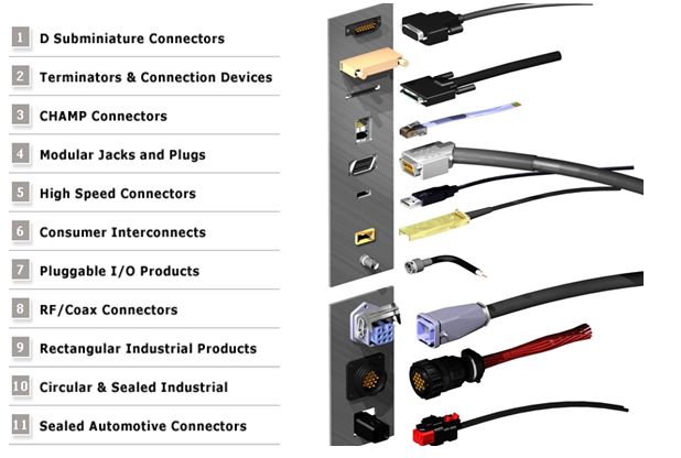
5.0 Brief classification of connectors:
In 1989, with the support of the National Electronic Distributors Association (NEDA, which is an industrial education organization), the industry leaders who produce connectors developed a connector classification standard and terminology.
|
Common Connector Types |
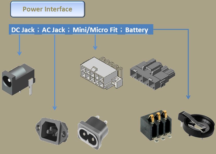
Power | DC Jack, AC Jack, Mini/Micro Fit, Battery |
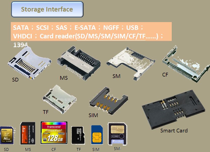
| Storage | SATA/SAS, SCSI, E-SATA, NGFF, USB, VHDCI, Card Reader | |
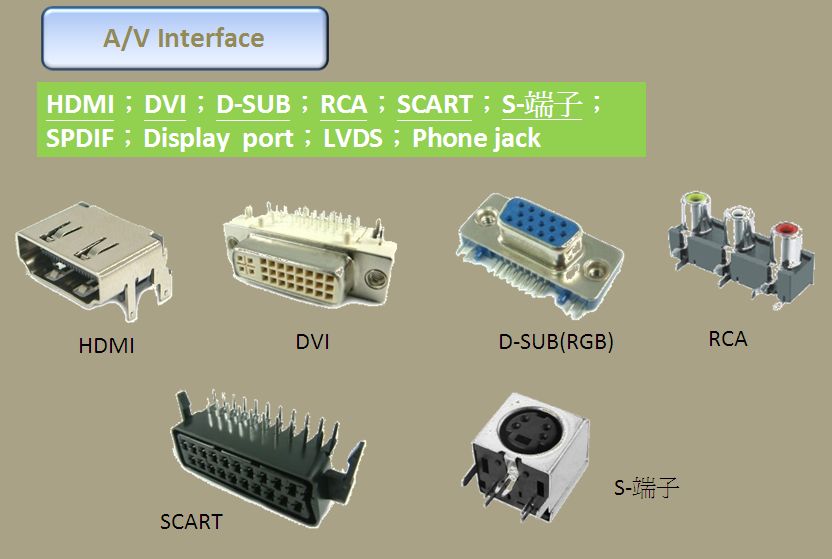
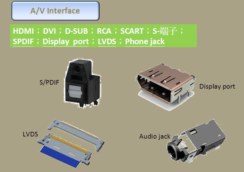
| Audio/Video | HDMI, DVI, D-SUB, RCA, SCART, SPDIF, Display Port, LVDS, Phone Jack | |
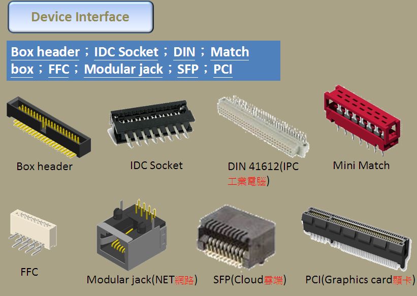
| Devices | Box Header, IDC Socket, DIN, Match Box, FFC, Modular Jack, SFP, PCI | |
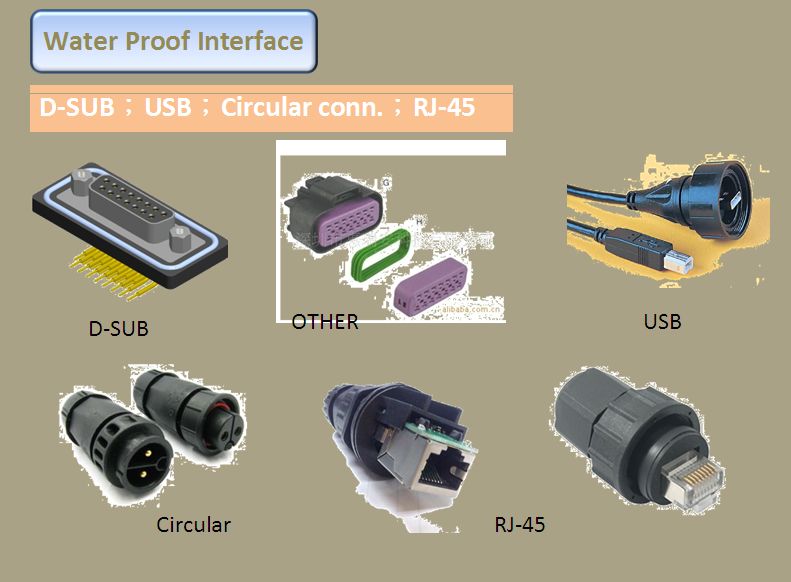
| Water Proof | D-Sub, USB, Circular Conn, RJ45 | |
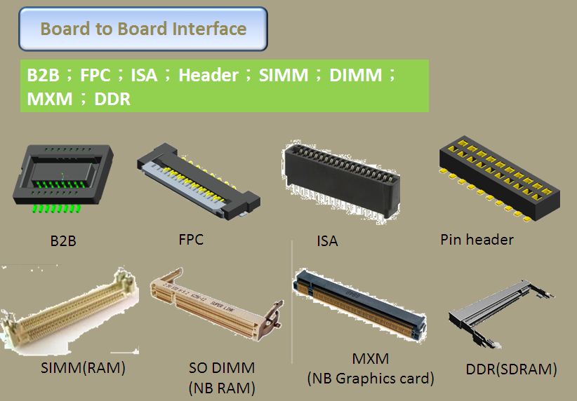
| Board to Board | B2B, FPC, ISA, Header, SIMM, DIMM, DDR | |
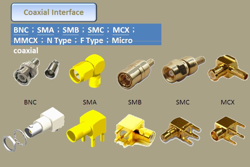
| Coaxial | BNC, SMA, SMB, SMC, MCX, MMCX, N Type, F Type, Micro Coaixal |
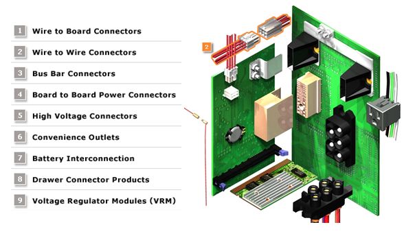
6.0 Brief application of the connector


7.0 Composition of the connector
- Housing
- Contacts – Terminals and pins
- Male and Female
- key and positioning
- Header
- Metal for connectors
- Coating
- Circuit identification
- Wire gauge (wire gauge)
The connector body has the following functions:
- Support the contact parts (pins, reeds, etc.), firmly and correctly in place;
- Dustproof, fouling and moisture-proof, protect contact parts and conductors;
- Insulate circuits from each other
The connector mounted on a printed circuit board is called a header, also known as a base or wafer. The main difference between the base and the seat body is that the base is always mounted with the circuit pins, while the seat body is just an empty shell. The base comes in two forms: covered and uncovered. The shield refers to the pins and sockets of the connector, and the protective cover made of the seat or skirt around the intersecting part. The base also has a friction lock style, which is a partially covered base, but has a locking device, which makes the base and the seat body combined.
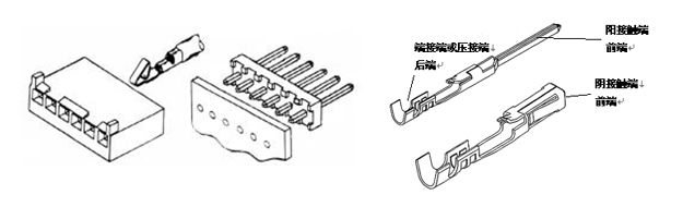
CONTACTS
The contact part of a connector holds together two parts of conductors (or wires) to be connected. Once bonded, the circuit is switched on and current flows through the connector. There are two main types of contacts: terminals and pins. The exact shape of the object varies. Illustrations of both are shown below. The terminal (or pin) has two ends: a front end and a rear end. The front end is always the joint end, which intersects with the other terminal to form contact. The rear end always terminates, either crimping or connecting wires (conductors) (see diagram below).
The metal used in the contact part of the connector
| Metal | Materials | Advantages | Disadvantages |
| Brass | Copper and zinc |
|
It is easy to crack due to stress and corrosion |
| Phosphor bronze | Copper and tin | It is more elastic than brass and stronger than brass |
|
| Cymbal copper | Copper and cymbals |
|
|
|
Coated metal |
Features |
|
Tin and tin-lead alloys |
|
|
Gold |
|
|
Palladium-nickel (with a thin layer of gold plated) |
|
|
Nickel |
|
8.0 Electrical performance of connectors:
The main electrical properties of connectors include contact resistance, insulation resistance, and electrical strength.
▶ Contact resistance: A high-quality electrical connector should have a low and stable contact resistance. The contact resistance of connectors varies from a few milliohms to tens of milliohms.
▶ Insulation resistance: A measure of the insulation performance between electrical connector contacts and between contacts and housings, ranging in the order of magnitude from hundreds of megaohms to thousands of gigaohms
▶ Electrical strength, or voltage resistance, is the ability to withstand the rated test voltage between connector contacts or between contacts and housings.
▶ Other electrical properties
Electromagnetic interference leakage attenuation is to evaluate the electromagnetic interference shielding effect of the connector, and electromagnetic interference leakage attenuation is to evaluate the electromagnetic interference shielding effect of the connector, which is generally tested in the frequency range of 100MHz~10GHz.
In the case of RF coaxial connectors, there are also electrical indicators such as characteristic impedance, insertion loss, reflection coefficient, and voltage standing wave ratio (VSWR). Due to the development of digital technology, in order to connect and transmit high-speed digital pulse signals, a new type of connector, namely high-speed signal connectors, has emerged, correspondingly, in terms of electrical performance, in addition to the characteristic impedance, some new electrical indicators have also appeared, such as crosstalk, transmission delay, time delay (skew), etc.
9.0 Physical properties of the connector:
Common environmental properties include low temperature, constant damp heat, alternating damp heat, salt spray test, sulfur dioxide test, hydrogen sulfide test.
▶ Temperature resistance: At present, the maximum working temperature of the connector is 200°C (except for a few high-temperature special connectors), and the minimum temperature is -65°C. Since the current generates heat at the contact point when the connector is operating, causing the temperature to rise, it is generally believed that the operating temperature should be equal to the sum of the ambient temperature and the temperature rise of the contact. In some specifications, the maximum allowable temperature rise of the connector at the rated operating current is clearly specified.
▶ Resistance to moisture intrusion can affect the insulation performance of the connection and corrode the metal parts. The constant damp heat test conditions are relative humidity 90%~95% (up to 98% according to product specifications), temperature +40±20°C, and the test time is at least 96 hours according to the product regulations. The alternating damp heat test is more stringent.
▶ Salt spray resistance When the connector works in an environment containing moisture and salt, the surface treatment layer of the metal structure and contact parts may cause galvanic corrosion, which will affect the physical and electrical properties of the connector. In order to evaluate the ability of electrical connectors to withstand this environment, a salt spray test is prescribed. It is to suspend the connector in a temperature-controlled test chamber and spray it with compressed air with a specified concentration of sodium chloride solution to form a salt spray atmosphere, and its exposure time is specified by the product specification for at least 48 hours.
▶ Vibration and shock Resistance to vibration and shock is an important performance of electrical connectors, especially in special application environments such as aviation and aerospace, railway and road transportation, it is an important indicator to test the robustness of the mechanical structure of electrical connectors and the reliability of electrical contact. It is clearly specified in the relevant test methods. The peak acceleration, duration, and waveform of the shock pulse should be specified in the shock test, as well as the time of interruption of electrical continuity.
▶ Other environmental properties According to the requirements of use, other environmental properties of electrical connectors include tightness (air leakage, liquid pressure), liquid impregnation (resistance to specific liquids), low air pressure, etc.