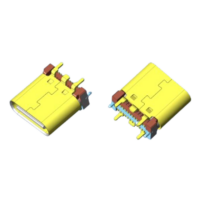
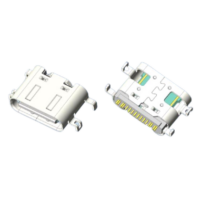
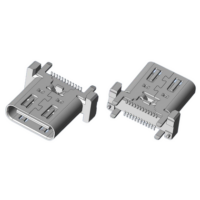
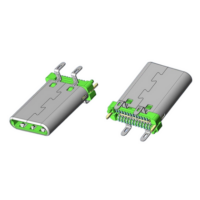
USB Type-C 16 Pin Vertical SMT Receptacle Connector UC22-1E1H1A103-0HR-29 (Molex 2193200001)
The UC22-1E1H1A103-0HR-29 is a USB Type-C 16-pin vertical SMT receptacle connector featuring high-temp UL94 V-0 rated housing, stainless steel shell, and copper alloy gold-plated contacts. Available with or without grounding spring, rated for 10,000 mating cycles and 5 A on VBUS/GND pins. IR reflow compatible at 260°C peak. RoHS compliant. Tape-and-reel packaging.
Product Overview
| Part Number | UC22-1E1H1A103-0HR-29 (see variants below) |
| Connector Type | USB Type-C Receptacle |
| Number of Pins | 16 |
| Mounting Style | Vertical / Upright SMT |
| Variant Options | With spring or without spring |
| RoHS Compliant | Yes |
Part Number Variants
| Part Number | DIM A | DIM B | DIM C | DIM D | Spring | Qty/Reel | Qty/Box |
|---|---|---|---|---|---|---|---|
| UC22-1E1H1A103-0HR-29 | 8.80 | 4.45 | 9.75 | 2.10 | With | 450 pcs | 4,500 pcs |
| UC22-2E1H1A103-0HR-29 | 9.20 | 4.95 | 10.20 | 1.70 | With | 450 pcs | 4,500 pcs |
| UC22-3E1H1A103-0HR-29 | 10.45 | 6.20 | 11.40 | 0.45 | With | 450 pcs | 4,500 pcs |
| UC22-1E1H1A103-1HR-29 | 8.80 | 4.45 | 9.75 | 2.10 | Without | 450 pcs | 4,500 pcs |
| UC22-2E1H1A103-1HR-29 | 9.20 | 4.95 | 10.20 | 1.70 | Without | 450 pcs | 4,500 pcs |
| UC22-3E1H1A103-1HR-29 | 10.45 | 6.20 | 11.40 | 0.45 | Without | 450 pcs | 4,500 pcs |
Product Specifications
Mechanical
| Parameter | Value |
|---|---|
| Housing | High-temp plastic, UL94 V-0 |
| Contact Material | Copper Alloy (C18150) |
| Shell / Mid Plate | Stainless Steel (SUS304) |
| Insertion / Removal Force | 0.5–2.0 kgf / 0.8–2.0 kgf |
| Mating Cycles | 10,000 cycles |
| Recommended PCB Thickness | 1.0 ± 0.10 mm |
Electrical
| Parameter | Value |
|---|---|
| Voltage Rating | 5 V DC/AC (RMS max) |
| Current — VBUS/GND Pins | 5 A total |
| Current — CC Pin | 1.25 A |
| Current — All Other Contacts | 0.25 A |
| LLCR — VBUS, GND & Others | 40 mΩ/pin max |
| LLCR Change of All Pins | 10 mΩ max |
| Insulation Resistance | 100 MΩ min |
| Dielectric Withstand Voltage | AC 100 V / 1 min |
Environmental
| Parameter | Value |
|---|---|
| Operating Temperature | -25°C ~ +85°C |
| IR Reflow Peak | 260°C / 10 sec |
16-Pin Signal Assignment
| Pin | Signal | Pin | Signal |
|---|---|---|---|
| A1 | GND | B1 | GND |
| A2 | VBUS | B2 | VBUS |
| A3 | CC1 | B3 | CC2 |
| A4 | D+ | B4 | D+ |
| A5 | D− | B5 | D− |
| A6 | SBU1 | B6 | SBU2 |
| A7 | VBUS | B7 | VBUS |
| A8 | GND | B8 | GND |
Product Features
- USB Type-C 16-pin full-featured layout
- Vertical SMT mounting for space-efficient PCB integration
- Available with or without grounding spring to suit different EMC requirements
- Stainless steel shell (SUS304) for superior EMI shielding
- UL94 V-0 flame-retardant housing for safety-critical applications
- Gold-plated contacts (Au 3 µin, Au 15 µin, or Au 30 µin options) for reliable, low-resistance performance
- 5 A VBUS/GND rating supports USB Power Delivery
- 10,000-cycle durability for long-life applications
- IR reflow compatible — peak 260°C for automated SMT assembly
- RoHS compliant
Applications
- Consumer electronics & smart devices
- IoT modules & edge computing hardware
- Industrial control & automation systems
- Automotive infotainment & ECUs
- Wearables & portable medical devices
- USB-PD chargers & power bank modules
- Networking & communication equipment
Packing Details
| Packaging | Embossed Tape & Reel |
| Qty / Reel | 450 pcs |
| Qty / Box | 4,500 pcs (10 reels) |
| Reel Diameter | Ø380 mm |
| Tape Width | 16 mm |
| Peeling Angle | 165°–180° |
FAQ
Q1: What is the difference between the variants with and without a grounding spring?
The grounding spring variant (suffix -0HR) includes an integrated spring on the shield for enhanced EMI suppression and a more secure mechanical ground to the PCB. The non-spring variant (suffix -1HR) omits this spring and is suitable for applications where the PCB provides sufficient grounding or where spring retention is not required. Select based on your EMC design and mechanical retention requirements.
Q2: What gold plating thickness options are available for the contacts?
Three options are available per P/N code: Au 3 µin (03), Au 15 µin (15), and Au 30 µin (30) on the contact functional area. Au 3 µin suits standard consumer applications; Au 15 µin is recommended for industrial environments with higher mating cycles; Au 30 µin provides maximum durability and corrosion resistance for harsh conditions. All solder areas use Au 1 µin flash plating with Ni 50 µin underplating.
Q3: How does the IR reflow profile affect the connector, and what should I watch out for?
The connector tolerates a peak board temperature of 260°C maintained for 10 seconds during IR reflow. Ensure that the temperature profile does not exceed these values or extend the time above 260°C, as this may affect the UL94 V-0 housing material integrity. Recommended PCB thickness is 1.0 ± 0.10 mm with a default tolerance of ±0.05 mm on the PCB layout.