When designing a printed circuit board (PCB), connector selection often feels like a minor detail—until it isn’t. The pitch (spacing between contacts) of your connector can impact everything from signal integrity to board size and manufacturing cost. Among the most common options, 1.0mm, 1.27mm, and 2.54mm pitch connectors each serve distinct purposes. This guide will help you navigate the trade-offs and make the right choice for your application.
What Is “Pitch” and Why Does It Matter?
Pitch is the distance between the center of one contact pin to the center of the next. It directly determines:
- Density: How many connections you can fit in a given space
- Current capacity: Wider pitches typically handle higher current
- Manufacturability: Larger pitches are easier to assemble and inspect
- Cost: Standard pitches (like 2.54mm) are generally cheaper and more available
The Three Contenders: A Quick Overview
- 1.0mm Pitch Connectors
The smallest of the trio, 1.0mm pitch connectors are the go-to for **high-density, space-constrained** designs. Common in consumer electronics, wearables, and modern smartphones, they pack maximum functionality into minimal real estate. However, their compact size comes with challenges: lower current ratings (typically 1A per pin) and more demanding assembly requirements. - 1.27mm Pitch Connectors
Often considered the **”sweet spot”** between density and usability. These connectors are popular in industrial equipment, medical devices, and IoT hardware. They offer better current handling than 1.0mm (around 1.5-2A) while remaining compact enough for most modern designs. Their footprint is also less prone to soldering defects during manufacturing. - 2.54mm Pitch Connectors
The **venerable standard** that has been around since the dawn of PCB design. Familiar from breadboards and Arduino shields, 2.54mm connectors excel in prototyping, hobbyist projects, and legacy industrial systems. They support higher currents (3A+), are the easiest to hand-solder, and offer the broadest selection of vendors and variants.
Key Decision Factors: A Deep Dive
1. Space Constraints
- 1.0mm: Choose when every millimeter counts—think smartwatches, earbuds, or ultra-compact sensors.
- 1.27mm: Ideal when you need moderate density without pushing manufacturing limits.
- 2.54mm: Best when board space is abundant, or you need to maintain compatibility with existing standards.
2. Current and Voltage Requirements
Always check the connector’s datasheet, but general guidelines apply:
- High power (>2A per pin): 2.54mm is your safest bet
- Moderate power (1-2A): 1.27mm offers a good balance
- Low power (<1A): 1.0mm saves space without compromising performance
3. Manufacturing and Assembly
- Automated assembly: All three pitches work with pick-and-place machines, but 1.0mm requires tighter tolerances and higher-end equipment.
- Hand soldering: 2.54mm is beginner-friendly; 1.27mm is challenging but doable; 1.0mm is nearly impossible for manual rework.
- Inspection: Larger pitches make automated optical inspection (AOI) and manual quality checks more reliable.
4. Signal Integrity
- High-speed signals: Shorter pitches can increase crosstalk. For differential pairs or high-frequency signals (>1 GHz), 1.27mm or 2.54mm with proper ground shields often outperform dense 1.0mm connectors.
- Shielding options: 2.54mm connectors have the widest variety of shielded versions for EMI-sensitive applications.
5. Cost and Availability
- 2.54mm: Most cost-effective due to economies of scale. Generic versions are pennies per pin.
- 1.27mm: Moderately priced with good availability from major suppliers.
- 1.0mm: Premium price point; lead times can be longer for specialized variants.
6. Mating Cycles and Durability
- Frequent mating: 2.54mm connectors (especially board-to-wire types) typically offer higher durability ratings (1000+ cycles).
- Permanent/semi-permanent: For internal connections rarely touched after assembly, 1.0mm and 1.27mm are perfectly adequate.
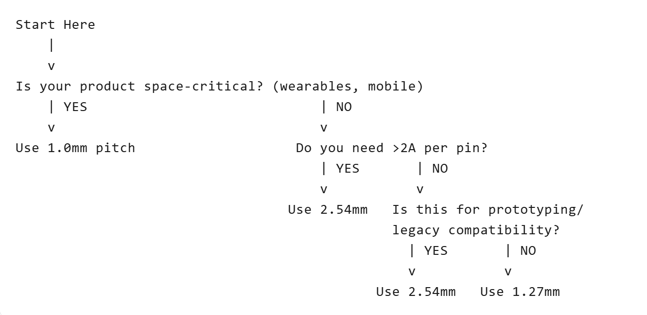
Decision Flowchart: Which Pitch Is Right for You?
Real-World Scenarios
- Scenario 1: IoT Environmental Sensor
– Needs: Compact size, moderate current (500mA), occasional field service
– Choice: 1.27mm — Provides enough density for 8-10 signals without making field repairs impossible - Scenario 2: Smartwatch Display Module
– Needs: Ultra-thin profile, low current (<200mA), high-volume manufacturing
– Choice: 1.0mm — Maximizes space efficiency; automated assembly eliminates hand-soldering concerns - Scenario 3: Industrial Motor Controller
– Needs: 5A power supply, rugged environment, long-term availability
– Choice: 2.54mm — Handles current comfortably, easy to service, and replacement parts available for 10+ years
Pro Tips for PCB Layout
Regardless of pitch, follow these best practices:
- Add keepouts: Leave 2-3mm clearance around connectors for mating/unmating tools
- Mechanical stability: Use mounting posts or screws for connectors subject to vibration
- Polarization: Choose keyed/shrouded connectors to prevent reverse insertion
- Test points: For 1.0mm and 1.27mm pitches, add test pads for debugging
- Datasheet discipline: Always verify mated height and footprint tolerances—they vary significantly between manufacturers
The Hybrid Approach
Many successful designs use multiple pitches. For example:
- 2.54mm for power input and programming headers
- 1.27mm for internal board-to-board connections
- 1.0mm for FPC cable to a display
This approach optimizes each connection for its specific requirements rather than forcing a one-size-fits-all solution.
Final Verdict
| Pitch | Best For | Avoid If… |
| 1.0mm | Ultra-compact, high-volume consumer tech | Hand assembly, high current, cost-sensitive projects |
| 1.27mm | Balanced modern designs, IoT, industrial | You need maximum current or absolute lowest cost |
| 2.54mm | Prototyping, power applications, legacy systems | Space is extremely limited or you need high pin density |
Conclusion
Choosing the right connector pitch is about balancing competing priorities: space vs. serviceability, density vs. current, and cost vs. performance. For most professional projects starting in 2025, 1.27mm offers the best all-around compromise. However, let your specific application requirements—not trends—drive the final decision.
When in doubt, prototype with 2.54mm headers for easy debugging, then transition to 1.27mm or 1.0mm in your production design once the pinout is finalized. Your future self (and your assembly house) will thank you.
Pro Tip
Always refer to the manufacturer’s datasheet for mechanical, electrical, and thermal specifications. For example, VITALCONN’s connector series include detailed PCB layout guides to ensure optimal performance.
Choose wisely—your connector pitch can make or break your PCB’s functionality!
What’s your experience with connector selection? Share your thoughts in the comments below!
#PCBDesign #Connectors #Electronics #Engineering #VITALCONN