Productos relacionados
-
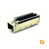 SFP Cage&CONN ConnectorSFP+ 1X1 Ganged Cage Press Fit, with Heatsink S2N3108055NA4
 -
-
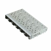 SFP+ Cage ConnectorSFP+ Cage Connector 1X6 Port Press Fit S2N3600100NA4
 -
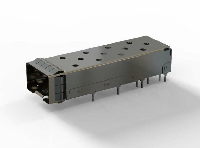
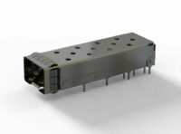 SFP+ Cage ConnectorSFP+ Cage Connector 1X1 Port with grounding pin, solder tail PN#S2N31Y0100NA4